目次
前
次
シリアルインタフェース
 シリアルインタフェースを使えるようすると
 他の内蔵モジュールに関連する処理や情報を
 扱いやすくなります。


 シリアル処理では、相手からのコマンド、パラメータを
 確実に受取り、取りこぼさないように受信割込みを使い
 ます。

 受信バッファは、リング構造にした方が、使い勝手が
 よいのですが、内蔵SRAMが少ないPICでは、メモリが
 枯渇しやすいため、利用しません。


 配列をサイズが8の倍数になるように確保し、受信文字を
 保存します。相手が送信してくるコマンド、パラメータは
 レコード単位で扱います。

 配列sbufを受信割込みで取得した文字を保存するバッファに利用。
 配列のどこに文字を格納するのかを指定するためにsindexを使い
 ます。

 1文字受信するたびに、バッファに保存していき
 変数sindexを更新します。

void interrupt(void)
{
  UBYTE chx ;
  /* receive interrupt */
  if ( PIR1.RCIF == ON ) {
    /* clear flag */
    PIR1.RCIF = OFF ;
    /* get 1 charactor */
    chx = RCREG ;
    /* store */
    *(sbuf+sindex) = chx ;
    /* increment */
    sindex++ ;
    /* judge */
    if ( chx == '\r' ) {
      sindex = 0 ;
      rflag = ON ;
    }
  }
}

 この処理は、MikroCでPIC12F629を使った場合。
 CCSのCでは、次のように記述します。

#int_rda

void echo_handler(void)
{
  UBYTE chx ;

  /* get one character */
  chx = getc() ;
  *(sbuf+sindex)= chx ;
  /* update buffer index */
  sindex++ ;
  /* judge */
  if ( chx == '\r' ) {
    sflag  = ON ;
    sindex = 0 ;
  }
}


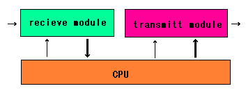
 受信モジュールは、8ビットレジスタとシリアル
 入力シフトレジスタで構成されています。


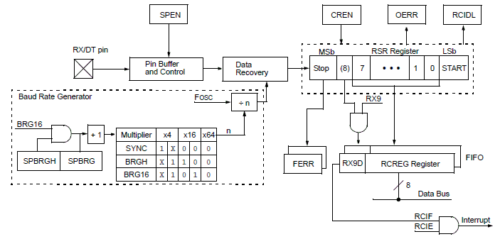
 ブロック図を見ると、受信関連のレジスタは
 以下があると言えます。
受信した場合、いろいろなエラーが発生する可能性が
あるので、それらをOERR、FERRのようなフラグにハード
が設定されると理解します。
受信モジュールを利用できるように、いろいろと
該当ビットのセット、リセットが必要だとわかります。
受信割込みを許可して、割込みハンドラの中に
受信バッファに文字を格納する処理をいれます。
1レコード受信終了後、フラグで通知すること
にすると、コマンドインタプリタを動かせます。
コマンドインタプリタは、次のように定義すればOK。
if ( rflag == ON ) {
/* clear */
rflag = OFF ;
/* new line */
crlf();
/* get command */
cmd = *(sbuf+0) ;
/* help */
if ( cmd == '?' ) { show_help() ; }
/* show A/D value */
if ( cmd == 'A' ) {
}
/* enable PWM */
if ( cmd == 'E' ) {
}
/* disable PWM */
if ( cmd == 'D' ) {
}
/* set forward duty ratio */
if ( cmd == 'F' ) {
}
/* set reverse ratio */
if ( cmd == 'R' ) {
}
/* show duty ratio */
if ( cmd == 'S' ) {
}
/* set number */
if ( cmd == 'N' ) {
}
/* show number */
if ( cmd == 'n' ) {
}
受信処理は、コマンドインタプリタの中に入れ
送信処理を考えます。
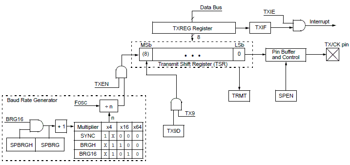
送信モジュールのブロック図を見ます。
 ブロック図を見ると、送信関連のレジスタは
以下があると言えます。
送信モジュールを利用できるように、いろいろと
該当ビットのセット、リセットが必要だとわかります。
送信では、マイコン側が自分のタイミングで
出力すればよいので、1文字送信関数を定義
し、その上に文字列送信、改行等の関数を
加えます。
1文字送信を定義して、その関数を土台にして
ラッパー関数を記述します。
void rs_putchar(UBYTE x)
{
/* judge */
while ( !TXSTA.TRMT ) ;
/* set data */
TXREG = x ;
}
void rs_puts(UBYTE *ptr)
{
while ( *ptr ) {
rs_putchar( *ptr );
ptr++ ;
}
crlf();
}
void crlf(void)
{
rs_putchar('\r');
rs_putchar('\n');
}
送信ではパラレル→シリアルのシフトレジスタが
空になっていなければ、レジスタに文字を入れる
と、データが破壊されるので、チェックが必要。
CCSのCでは、1文字送信は用意されているので
文字列送信は、次のように定義できます。
void rs_puts(UBYTE *ptr)
{
while ( *ptr ) {
putc( *ptr );
ptr++ ;
}
crlf();
}
CCSのCでは、printfはシリアルインタフェースに
限定して利用できるので、文字や文字列の送信は
printfでまとめてもよいでしょう。
最後に、MikroCでPIC16F688に接続したモータを
動かすソースコードを記します。
/* redefine data type */
typedef unsigned char UBYTE ;
typedef unsigned int UWORD ;
typedef unsigned long ULONG ;
#define OFF 0
#define ON OFF+1
#define PM_BIT 2
#define RX_BIT 5
#define TX_BIT 4
#define ENABLE_PWM 3
#define F_BIT 4
#define R_BIT 5
#define ADST_BIT 1
#define PCNTMAX 100
#define MASKFF 0xff
#define MASK30 0x30
#define MASK0F 0x0f
#define MASK03 0x03
#define MASK3FF 0x3ff
volatile ULONG timcnt ;
volatile UBYTE rflag ;
volatile UBYTE sbuf[8] ;
volatile UBYTE sindex ;
volatile UBYTE cmd ;
volatile UWORD adv ;
volatile UBYTE xmsg[5] ;
volatile UBYTE loop ;
volatile UBYTE pcnt ;
volatile UBYTE fcnt ;
volatile UBYTE rcnt ;
volatile UBYTE fcntx ;
volatile UBYTE rcntx ;
/* function prototype */
void init_usr(void);
void delay_ms(UWORD x);
void rs_putchar(UBYTE x);
void rs_puts(UBYTE *ptr);
void crlf(void);
UBYTE get_hex(UBYTE x);
UWORD get_adv(void);
void show_help(void);
/* interrupt handler */
void interrupt(void)
{
UBYTE chx ;
/* generate 1ms */
if ( INTCON.T0IF == ON ) {
/* clear flag */
INTCON.T0IF = OFF ;
/* initialize */
TMR0 = 6 ;
/* increment */
timcnt++ ;
/* increment PWM counter */
pcnt++ ;
if ( pcnt == PCNTMAX ) {
pcnt = 0 ;
fcntx = fcnt ;
rcntx = rcnt ;
}
/* impress */
if ( pcnt < fcntx ) { PORTA.B4 = ON ; }
else { PORTA.B4 = OFF ; }
if ( pcnt < rcntx ) { PORTA.B5 = ON ; }
else { PORTA.B5 = OFF ; }
}
/* receive interrupt */
if ( PIR1.RCIF == ON ) {
/* clear flag */
PIR1.RCIF = OFF ;
/* get 1 charactor */
chx = RCREG ;
/* store */
*(sbuf+sindex) = chx ;
/* increment */
sindex++ ;
/* judge */
if ( chx == '\r' ) {
sindex = 0 ;
rflag = ON ;
}
}
}
void main(void)
{
/* user initialize */
init_usr();
/* endless loop */
while ( ON ) {
/* command interpreter */
if ( rflag == ON ) {
/* clear */
rflag = OFF ;
/* new line */
crlf();
/* get command */
cmd = *(sbuf+0) ;
/* help */
if ( cmd == '?' ) { show_help() ; }
/* show A/D value */
if ( cmd == 'A' ) {
/* get A/D value */
adv = get_adv();
/* calculate digit and conversion */
*(xmsg+0) = (adv / 1000) + '0' ; adv %= 1000 ;
*(xmsg+1) = (adv / 100 ) + '0' ; adv %= 100 ;
*(xmsg+2) = (adv / 10 ) + '0' ;
*(xmsg+3) = (adv % 10 ) + '0' ;
/* show */
rs_puts( xmsg );
}
/* enable PWM */
if ( cmd == 'E' ) {
if ( *(sbuf+1) == '1' ) { PORTA.B3 = ON ; }
else { PORTA.B3 = OFF ; }
}
/* disable PWM */
if ( cmd == 'D' ) { PORTC &= ~(1 << ENABLE_PWM) ; }
/* set forward duty ratio */
if ( cmd == 'F' ) {
fcnt = get_hex( *(sbuf+1) ) ;
fcnt *= 10 ;
fcnt |= get_hex( *(sbuf+2) ) ;
/* clear */
rcnt = 0 ;
}
/* set reverse ratio */
if ( cmd == 'R' ) {
rcnt = get_hex( *(sbuf+1) ) ;
rcnt *= 10 ;
rcnt |= get_hex( *(sbuf+2) ) ;
/* clear */
fcnt = 0 ;
}
/* show duty ratio */
if ( cmd == 'S' ) {
/* forward */
*(xmsg+0) = 'F' ;
*(xmsg+1) = ':' ;
*(xmsg+2) = fcnt / 10 + '0' ;
*(xmsg+3) = fcnt % 10 + '0' ;
for ( loop = 0 ; loop < 4 ; loop++ ) {
rs_putchar( *(xmsg+loop) );
}
rs_puts("%");
/* reverse */
*(xmsg+0) = 'R' ;
*(xmsg+1) = ':' ;
*(xmsg+2) = rcnt / 10 + '0' ;
*(xmsg+3) = rcnt % 10 + '0' ;
for ( loop = 0 ; loop < 4 ; loop++ ) {
rs_putchar( *(xmsg+loop) );
}
rs_puts("%");
}
}
}
}
/* define function body */
void init_usr(void)
{
/* I/O initial state */
PORTA = 0x00 ;
PORTC = (1 << RX_BIT);
/* I/O direction */
TRISA = (1 << PM_BIT) ;
TRISC = (1 << RX_BIT) ;
/* disable compare module */
CMCON0 = 0x07 ;
/* pull-up */
WPU = 0x14 ;
/* initialize A/D converter */
{
/* select A/D bits */
ANSEL = (1 << PM_BIT) ;
/* enable A/D converter */
ADCON0.ADON = ON ;
/* right justify */
ADCON0.ADFM = ON ;
/* select reference voltage */
ADCON0.VCFG = ON ;
/* select RA2 */
ADCON0 &= ~0x1c ;
ADCON0 |= (2 << 2);
/* select A/D frequency */
ADCON1 = 0 ;
}
/* initialize serial interface */
{
sindex = 0 ;
/* BAUD rate */
BAUDCTL.BRG16 = ON ;
SPBRG = 103 ; /* 9600bps */
/* TxD */
TXSTA.TXEN = ON ;
TXSTA.SYNC = OFF ;
TXSTA.BRGH = ON ;
/* RxD */
RCSTA.SPEN = ON ;
RCSTA.CREN = ON ;
/* enable receive interrupt */
PIE1.RCIE = ON ;
INTCON.PEIE = ON ;
}
/* initialize Timer 0 */
{
/*
4MHz/4 = 1MHz -> 1MHz/4 = 250kHz prescaler = 1:4
all inputs are pull-up .
*/
OPTION_REG = 0x01 ;
/* 256 - 250 = 6 */
TMR0 = 6 ;
/* enable timer0 overflow interrupt */
INTCON.T0IE = ON ;
}
/* enable general interrupt */
INTCON.GIE = ON ;
/* clear flags */
rflag = OFF ;
/* others */
timcnt = 0 ;
*(xmsg+4) = 0 ;
pcnt = 0 ;
fcnt = 0 ;
rcnt = 0 ;
fcntx = 0 ;
rcntx = 0 ;
}
void delay_ms(UWORD x)
{
ULONG target ;
/* calculate */
target = timcnt + x ;
/* */
while ( timcnt < target ) ;
}
void rs_putchar(UBYTE x)
{
/* judge */
while ( !TXSTA.TRMT ) ;
/* set data */
TXREG = x ;
}
void rs_puts(UBYTE *ptr)
{
while ( *ptr ) {
rs_putchar( *ptr );
ptr++ ;
}
crlf();
}
void crlf(void)
{
rs_putchar('\r');
rs_putchar('\n');
}
UBYTE get_hex(UBYTE x)
{
UBYTE result ;
/* default */
result = 0 ;
/* convert */
if ( '0' <= x && x <= '9' ) { result = x - '0' ; }
if ( 'A' <= x && x <= 'F' ) { result = x - 'A' + 10 ; }
if ( 'a' <= x && x <= 'f' ) { result = x - 'a' + 10 ; }
return result ;
}
UWORD get_adv(void)
{
UWORD result ;
/* start conversion */
ADCON0 |= (1 << ADST_BIT);
/* wait */
while ( ADCON0 & (1 << ADST_BIT) ) ;
/* get data */
result = ADRESH ; /* upper */
result <<= 8 ;
result |= ADRESL ; /* lower */
/* mask */
result &= MASK3FF ;
return result ;
}
void show_help(void)
{
rs_puts("? help");
rs_puts("A get A/D value");
rs_puts("E enable or disable PWM");
rs_puts("F set forword duty");
rs_puts("R set reverse duty");
rs_puts("S show duty ratio");
}
このソースコードでは、A/D変換器で外部の電圧を
表示できます。数値から数字への変換も扱ってます。
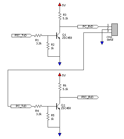
シリアルインタフェースの接続回路は、以下のように
しています。

目次
前
次

シリアル処理では、相手からのコマンド、パラメータを 確実に受取り、取りこぼさないように受信割込みを使い ます。 受信バッファは、リング構造にした方が、使い勝手が よいのですが、内蔵SRAMが少ないPICでは、メモリが 枯渇しやすいため、利用しません。
配列をサイズが8の倍数になるように確保し、受信文字を 保存します。相手が送信してくるコマンド、パラメータは レコード単位で扱います。 配列sbufを受信割込みで取得した文字を保存するバッファに利用。 配列のどこに文字を格納するのかを指定するためにsindexを使い ます。 1文字受信するたびに、バッファに保存していき 変数sindexを更新します。 void interrupt(void) { UBYTE chx ; /* receive interrupt */ if ( PIR1.RCIF == ON ) { /* clear flag */ PIR1.RCIF = OFF ; /* get 1 charactor */ chx = RCREG ; /* store */ *(sbuf+sindex) = chx ; /* increment */ sindex++ ; /* judge */ if ( chx == '\r' ) { sindex = 0 ; rflag = ON ; } } } この処理は、MikroCでPIC12F629を使った場合。 CCSのCでは、次のように記述します。 #int_rda void echo_handler(void) { UBYTE chx ; /* get one character */ chx = getc() ; *(sbuf+sindex)= chx ; /* update buffer index */ sindex++ ; /* judge */ if ( chx == '\r' ) { sflag = ON ; sindex = 0 ; } } 受信モジュールは、8ビットレジスタとシリアル 入力シフトレジスタで構成されています。
ブロック図を見ると、受信関連のレジスタは 以下があると言えます。