GBCモニタ装置
GameBoyCameraの出力データをモニタする装置を
作成して、デバッグ効率を上げるようにしました。
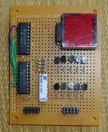
10x10のドットマトリクスLEDを利用した装置は
以下です。
 回路図は、以下です。
 10x10のドットマトリクスLEDなので、2つのコネクタで
操作できるよう、レジスタを2個、デコーダを1個利用
しています。
回路動作テストに、ATTiny2313で簡単なプログラムを
作成しました。
#include <avr/io.h>
#include <avr/interrupt.h>
#define OFF 0
#define ON OFF+1
typedef unsigned char UBYTE ;
typedef unsigned short UWORD ;
volatile UBYTE tflag ;
volatile UBYTE sflag ;
volatile UWORD ledx ;
volatile UWORD led_line[10] ;
volatile UBYTE lindex ;
volatile UWORD scnt ;
volatile UBYTE cnt ;
#define MASKFF 0xff
#define MASK1F 0x1f
#define MASK0F 0x0f
#define MASKF0 0xf0
#define LTRGU 0x80
#define LTRGL 0x40
#define SCNTMAX 4000
/*--------------------------------*/
/* Insert user functions protoype */
/*--------------------------------*/
void user_initialize(void);
void led_handling(void);
void init_led_pat(UBYTE x);
/*------*/
/* main */
/*------*/
int main(void)
{
/* disable interrupt */
cli();
/* initialize port and variables */
user_initialize();
/* enable interrupt */
sei();
/* endless loop */
cnt = 0 ;
while ( ON ) {
/* dot matrix LED handling */
if ( tflag ) {
tflag = OFF ;
led_handling();
}
/* update pattern */
if ( sflag ) {
sflag = OFF ;
/* update */
cnt++ ;
if ( cnt == 4 ) { cnt = 0 ; }
init_led_pat(cnt);
}
}
/* dummy */
return 0 ;
}
/*-----------------------*/
/* Insert user functions */
/*-----------------------*/
void user_initialize(void)
{
/* PORT B */
PORTB = 0b00000000 ; /* 00000000 */
DDRB = 0b11111111 ; /* oooooooo */
/* PORT D */
PORTD = 0b00000000 ; /* 00000000 */
DDRD = 0b11111111 ; /* oooooooo */
/* */
tflag = OFF ;
sflag = OFF ;
scnt = 0 ;
/* initialize timer0 */
{
/* CTC */
TCCR0A = (1 << WGM01);
/* 4MHz / 8 = 500kHz */
TCCR0B = (1 << CS01) ;
/* clear */
TCNT0 = 0 ;
/* set compare registers */
OCR0A = 249 ; /* generate 2kHz */
OCR0B = 255 ;
/* enable compare match interrupt */
TIMSK = (1 << OCIE0A);
}
/* initialize pattern */
lindex = 0 ;
init_led_pat(0);
}
void led_handling(void)
{
/* disable line */
PORTD = MASKFF ;
/* dot matrix LED handling */
ledx = *(led_line+lindex) ;
/* lower side */
PORTB = ((ledx & MASK1F) ^ MASK1F) | LTRGL ;
PORTB &= ~LTRGL ;
/* upper side */
ledx >>= 5 ;
PORTB = ((ledx & MASK1F) ^ MASK1F) | LTRGU ;
PORTB &= ~LTRGU ;
/* select line */
PORTD = lindex ;
/* update */
lindex++ ;
if ( lindex == 10 ) { lindex = 0 ; }
}
void init_led_pat(UBYTE x)
{
UBYTE i ;
/* clear */
for ( i = 0 ; i < 10 ; i++ ) { *(led_line+i) = 0 ; }
/* generate */
switch ( x ) {
case 1 :
*(led_line+0) = 0x03ff ;
*(led_line+1) = 0x03ff ;
*(led_line+2) = 0x03ff ;
*(led_line+3) = 0x03ff ;
*(led_line+4) = 0x03ff ;
break ;
case 2 :
*(led_line+5) = 0x03ff ;
*(led_line+6) = 0x03ff ;
*(led_line+7) = 0x03ff ;
*(led_line+8) = 0x03ff ;
*(led_line+9) = 0x03ff ;
break ;
case 3 :
*(led_line+0) = 0x0155 ;
*(led_line+2) = 0x0155 ;
*(led_line+4) = 0x0155 ;
*(led_line+6) = 0x0155 ;
*(led_line+8) = 0x0155 ;
*(led_line+1) = 0x02aa ;
*(led_line+3) = 0x02aa ;
*(led_line+5) = 0x02aa ;
*(led_line+7) = 0x02aa ;
*(led_line+9) = 0x02aa ;
break ;
default :
*(led_line+0) = 0x02aa ;
*(led_line+2) = 0x02aa ;
*(led_line+4) = 0x02aa ;
*(led_line+6) = 0x02aa ;
*(led_line+8) = 0x02aa ;
*(led_line+1) = 0x0155 ;
*(led_line+3) = 0x0155 ;
*(led_line+5) = 0x0155 ;
*(led_line+7) = 0x0155 ;
*(led_line+9) = 0x0155 ;
break ;
}
}
/* timer0 interrupt */
ISR(TIMER0_COMPA_vect)
{
tflag = ON ;
scnt++ ;
if ( scnt == SCNTMAX ) {
scnt = 0 ;
sflag = ON ;
}
}
動作は単純で、2秒ごとに4つの出力パターンを変更します。
表示は、0.5msごとに10ライン分のデータを74LS373に記憶させて
いきます。この処理はエンドレスで、マイコンに電源は供給中
ずっと繰り返します。
ファームウエアで実現した内容を、VHDLコードに変換し
CPLDのCoolRunnerIIでも動かしてみました。
library IEEE;
use IEEE.STD_LOGIC_1164.ALL;
use IEEE.STD_LOGIC_ARITH.ALL;
use IEEE.STD_LOGIC_UNSIGNED.ALL;
entity dledc is
generic (
TOPX : integer := 4 ;
RMAX : integer := 9 --;
);
port(
-- system
nRESET : in std_logic ;
CLOCK : in std_logic ;
-- output
LTRGU : out std_logic ;
LTRGL : out std_logic ;
LDAT : out std_logic_vector(4 downto 0) ;
LADR : out std_logic_vector(3 downto 0) --;
);
end dledc;
architecture Behavioral of dledc is
-- clock component
component clkgenx is
generic (
TOPX : integer ;
RMAX : integer --;
);
port (
-- system
nRESET : in std_logic ;
CLOCK : in std_logic ;
-- output
CLKOUT : out std_logic -- ;
);
end component ;
-- clock generator
signal iPCLK : std_logic ;
signal iCNT : integer range 0 to 200000 ;
signal iCYCLE : std_logic_vector( 1 downto 0) ;
-- run sequencer
signal iLDAT : std_logic_vector( 4 downto 0) ;
signal iLDATX : std_logic_vector(99 downto 0) ;
signal iLADR : integer range 0 to 15 ;
signal iPTR : integer range 0 to 90 ;
signal iSTATE : integer range 0 to 7 ;
begin
-- clock generator
CLKP : clkgenx generic map (TOPX,RMAX) port map (nRESET,CLOCK,iPCLK);
-- output
LTRGU <= '1' when ( iSTATE = 0 ) else '0' ;
LTRGL <= '1' when ( iSTATE = 2 ) else '0' ;
LDAT <= not iLDAT ;
LADR <= conv_std_logic_vector(iLADR,4) when ( iSTATE > 3 ) else "1111" ;
-- decode
iLDATX(99 downto 90) <= "1010101010" when (iCYCLE = 0) else
"1111111111" when (iCYCLE = 1) else
"0101010101" when (iCYCLE = 3) else
"0000000000" ;
iLDATX(89 downto 80) <= "1010101010" when (iCYCLE = 0) else
"1111111111" when (iCYCLE = 1) else
"0101010101" when (iCYCLE = 3) else
"0000000000" ;
iLDATX(79 downto 70) <= "1010101010" when (iCYCLE = 0) else
"1111111111" when (iCYCLE = 1) else
"0101010101" when (iCYCLE = 3) else
"0000000000" ;
iLDATX(69 downto 60) <= "1010101010" when (iCYCLE = 0) else
"1111111111" when (iCYCLE = 1) else
"0101010101" when (iCYCLE = 3) else
"0000000000" ;
iLDATX(59 downto 50) <= "1010101010" when (iCYCLE = 0) else
"1111111111" when (iCYCLE = 1) else
"0101010101" when (iCYCLE = 3) else
"0000000000" ;
iLDATX(49 downto 40) <= "1010101010" when (iCYCLE = 0) else
"1111111111" when (iCYCLE = 2) else
"0101010101" when (iCYCLE = 3) else
"0000000000" ;
iLDATX(39 downto 30) <= "1010101010" when (iCYCLE = 0) else
"1111111111" when (iCYCLE = 2) else
"0101010101" when (iCYCLE = 3) else
"0000000000" ;
iLDATX(29 downto 20) <= "1010101010" when (iCYCLE = 0) else
"1111111111" when (iCYCLE = 2) else
"0101010101" when (iCYCLE = 3) else
"0000000000" ;
iLDATX(19 downto 10) <= "1010101010" when (iCYCLE = 0) else
"1111111111" when (iCYCLE = 2) else
"0101010101" when (iCYCLE = 3) else
"0000000000" ;
iLDATX( 9 downto 0) <= "1010101010" when (iCYCLE = 0) else
"1111111111" when (iCYCLE = 2) else
"0101010101" when (iCYCLE = 3) else
"0000000000" ;
-- cyclic update
process (nRESET,iPCLK)
begin
if ( nRESET = '0' ) then
iCNT <= 0 ;
iCYCLE <= "00" ;
elsif rising_edge( iPCLK ) then
iCNT <= iCNT + 1 ;
if ( iCNT = 200000 ) then
iCNT <= 0 ;
iCYCLE <= iCYCLE + '1' ;
end if ;
end if ;
end process ;
-- sequnecer
process (nRESET,iPCLK)
begin
if ( nRESET = '0' ) then
iLDAT <= "00000" ;
iLADR <= 0 ;
iPTR <= 0 ;
iSTATE <= 0 ;
elsif rising_edge(iPCLK) then
-- state machine
case iSTATE is
-- send upper 5 bits
when 0 => iLDAT <= iLDATX(99-iPTR downto 95-iPTR) ;
iSTATE <= 1 ;
-- send upper trigger
when 1 => iSTATE <= 2 ;
-- send lower 5 bits
when 2 => iLDAT <= iLDATX(94-iPTR downto 90-iPTR) ;
iSTATE <= 3 ;
-- send lower trigger
when 3 => iSTATE <= 4 ;
-- enable address
when 4 => iSTATE <= 5 ;
-- update
when 5 => iLADR <= iLADR + 1 ;
iPTR <= iPTR + 10 ;
iSTATE <= 6 ;
-- return first state
when 6 => iSTATE <= 0 ;
if ( iLADR = 10 ) then
iLADR <= 0 ;
iPTR <= 0 ;
end if ;
-- default
when others =>
iSTATE <= 0 ;
end case ;
end if ;
end process ;
end Behavioral;
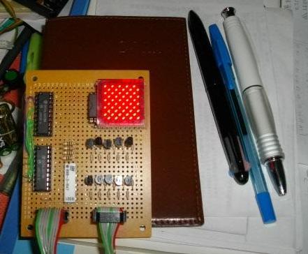
データパターンを出力すると、次のようになります。
10x10のドットマトリクスLEDなので、2つのコネクタで
操作できるよう、レジスタを2個、デコーダを1個利用
しています。
回路動作テストに、ATTiny2313で簡単なプログラムを
作成しました。
#include <avr/io.h>
#include <avr/interrupt.h>
#define OFF 0
#define ON OFF+1
typedef unsigned char UBYTE ;
typedef unsigned short UWORD ;
volatile UBYTE tflag ;
volatile UBYTE sflag ;
volatile UWORD ledx ;
volatile UWORD led_line[10] ;
volatile UBYTE lindex ;
volatile UWORD scnt ;
volatile UBYTE cnt ;
#define MASKFF 0xff
#define MASK1F 0x1f
#define MASK0F 0x0f
#define MASKF0 0xf0
#define LTRGU 0x80
#define LTRGL 0x40
#define SCNTMAX 4000
/*--------------------------------*/
/* Insert user functions protoype */
/*--------------------------------*/
void user_initialize(void);
void led_handling(void);
void init_led_pat(UBYTE x);
/*------*/
/* main */
/*------*/
int main(void)
{
/* disable interrupt */
cli();
/* initialize port and variables */
user_initialize();
/* enable interrupt */
sei();
/* endless loop */
cnt = 0 ;
while ( ON ) {
/* dot matrix LED handling */
if ( tflag ) {
tflag = OFF ;
led_handling();
}
/* update pattern */
if ( sflag ) {
sflag = OFF ;
/* update */
cnt++ ;
if ( cnt == 4 ) { cnt = 0 ; }
init_led_pat(cnt);
}
}
/* dummy */
return 0 ;
}
/*-----------------------*/
/* Insert user functions */
/*-----------------------*/
void user_initialize(void)
{
/* PORT B */
PORTB = 0b00000000 ; /* 00000000 */
DDRB = 0b11111111 ; /* oooooooo */
/* PORT D */
PORTD = 0b00000000 ; /* 00000000 */
DDRD = 0b11111111 ; /* oooooooo */
/* */
tflag = OFF ;
sflag = OFF ;
scnt = 0 ;
/* initialize timer0 */
{
/* CTC */
TCCR0A = (1 << WGM01);
/* 4MHz / 8 = 500kHz */
TCCR0B = (1 << CS01) ;
/* clear */
TCNT0 = 0 ;
/* set compare registers */
OCR0A = 249 ; /* generate 2kHz */
OCR0B = 255 ;
/* enable compare match interrupt */
TIMSK = (1 << OCIE0A);
}
/* initialize pattern */
lindex = 0 ;
init_led_pat(0);
}
void led_handling(void)
{
/* disable line */
PORTD = MASKFF ;
/* dot matrix LED handling */
ledx = *(led_line+lindex) ;
/* lower side */
PORTB = ((ledx & MASK1F) ^ MASK1F) | LTRGL ;
PORTB &= ~LTRGL ;
/* upper side */
ledx >>= 5 ;
PORTB = ((ledx & MASK1F) ^ MASK1F) | LTRGU ;
PORTB &= ~LTRGU ;
/* select line */
PORTD = lindex ;
/* update */
lindex++ ;
if ( lindex == 10 ) { lindex = 0 ; }
}
void init_led_pat(UBYTE x)
{
UBYTE i ;
/* clear */
for ( i = 0 ; i < 10 ; i++ ) { *(led_line+i) = 0 ; }
/* generate */
switch ( x ) {
case 1 :
*(led_line+0) = 0x03ff ;
*(led_line+1) = 0x03ff ;
*(led_line+2) = 0x03ff ;
*(led_line+3) = 0x03ff ;
*(led_line+4) = 0x03ff ;
break ;
case 2 :
*(led_line+5) = 0x03ff ;
*(led_line+6) = 0x03ff ;
*(led_line+7) = 0x03ff ;
*(led_line+8) = 0x03ff ;
*(led_line+9) = 0x03ff ;
break ;
case 3 :
*(led_line+0) = 0x0155 ;
*(led_line+2) = 0x0155 ;
*(led_line+4) = 0x0155 ;
*(led_line+6) = 0x0155 ;
*(led_line+8) = 0x0155 ;
*(led_line+1) = 0x02aa ;
*(led_line+3) = 0x02aa ;
*(led_line+5) = 0x02aa ;
*(led_line+7) = 0x02aa ;
*(led_line+9) = 0x02aa ;
break ;
default :
*(led_line+0) = 0x02aa ;
*(led_line+2) = 0x02aa ;
*(led_line+4) = 0x02aa ;
*(led_line+6) = 0x02aa ;
*(led_line+8) = 0x02aa ;
*(led_line+1) = 0x0155 ;
*(led_line+3) = 0x0155 ;
*(led_line+5) = 0x0155 ;
*(led_line+7) = 0x0155 ;
*(led_line+9) = 0x0155 ;
break ;
}
}
/* timer0 interrupt */
ISR(TIMER0_COMPA_vect)
{
tflag = ON ;
scnt++ ;
if ( scnt == SCNTMAX ) {
scnt = 0 ;
sflag = ON ;
}
}
動作は単純で、2秒ごとに4つの出力パターンを変更します。
表示は、0.5msごとに10ライン分のデータを74LS373に記憶させて
いきます。この処理はエンドレスで、マイコンに電源は供給中
ずっと繰り返します。
ファームウエアで実現した内容を、VHDLコードに変換し
CPLDのCoolRunnerIIでも動かしてみました。
library IEEE;
use IEEE.STD_LOGIC_1164.ALL;
use IEEE.STD_LOGIC_ARITH.ALL;
use IEEE.STD_LOGIC_UNSIGNED.ALL;
entity dledc is
generic (
TOPX : integer := 4 ;
RMAX : integer := 9 --;
);
port(
-- system
nRESET : in std_logic ;
CLOCK : in std_logic ;
-- output
LTRGU : out std_logic ;
LTRGL : out std_logic ;
LDAT : out std_logic_vector(4 downto 0) ;
LADR : out std_logic_vector(3 downto 0) --;
);
end dledc;
architecture Behavioral of dledc is
-- clock component
component clkgenx is
generic (
TOPX : integer ;
RMAX : integer --;
);
port (
-- system
nRESET : in std_logic ;
CLOCK : in std_logic ;
-- output
CLKOUT : out std_logic -- ;
);
end component ;
-- clock generator
signal iPCLK : std_logic ;
signal iCNT : integer range 0 to 200000 ;
signal iCYCLE : std_logic_vector( 1 downto 0) ;
-- run sequencer
signal iLDAT : std_logic_vector( 4 downto 0) ;
signal iLDATX : std_logic_vector(99 downto 0) ;
signal iLADR : integer range 0 to 15 ;
signal iPTR : integer range 0 to 90 ;
signal iSTATE : integer range 0 to 7 ;
begin
-- clock generator
CLKP : clkgenx generic map (TOPX,RMAX) port map (nRESET,CLOCK,iPCLK);
-- output
LTRGU <= '1' when ( iSTATE = 0 ) else '0' ;
LTRGL <= '1' when ( iSTATE = 2 ) else '0' ;
LDAT <= not iLDAT ;
LADR <= conv_std_logic_vector(iLADR,4) when ( iSTATE > 3 ) else "1111" ;
-- decode
iLDATX(99 downto 90) <= "1010101010" when (iCYCLE = 0) else
"1111111111" when (iCYCLE = 1) else
"0101010101" when (iCYCLE = 3) else
"0000000000" ;
iLDATX(89 downto 80) <= "1010101010" when (iCYCLE = 0) else
"1111111111" when (iCYCLE = 1) else
"0101010101" when (iCYCLE = 3) else
"0000000000" ;
iLDATX(79 downto 70) <= "1010101010" when (iCYCLE = 0) else
"1111111111" when (iCYCLE = 1) else
"0101010101" when (iCYCLE = 3) else
"0000000000" ;
iLDATX(69 downto 60) <= "1010101010" when (iCYCLE = 0) else
"1111111111" when (iCYCLE = 1) else
"0101010101" when (iCYCLE = 3) else
"0000000000" ;
iLDATX(59 downto 50) <= "1010101010" when (iCYCLE = 0) else
"1111111111" when (iCYCLE = 1) else
"0101010101" when (iCYCLE = 3) else
"0000000000" ;
iLDATX(49 downto 40) <= "1010101010" when (iCYCLE = 0) else
"1111111111" when (iCYCLE = 2) else
"0101010101" when (iCYCLE = 3) else
"0000000000" ;
iLDATX(39 downto 30) <= "1010101010" when (iCYCLE = 0) else
"1111111111" when (iCYCLE = 2) else
"0101010101" when (iCYCLE = 3) else
"0000000000" ;
iLDATX(29 downto 20) <= "1010101010" when (iCYCLE = 0) else
"1111111111" when (iCYCLE = 2) else
"0101010101" when (iCYCLE = 3) else
"0000000000" ;
iLDATX(19 downto 10) <= "1010101010" when (iCYCLE = 0) else
"1111111111" when (iCYCLE = 2) else
"0101010101" when (iCYCLE = 3) else
"0000000000" ;
iLDATX( 9 downto 0) <= "1010101010" when (iCYCLE = 0) else
"1111111111" when (iCYCLE = 2) else
"0101010101" when (iCYCLE = 3) else
"0000000000" ;
-- cyclic update
process (nRESET,iPCLK)
begin
if ( nRESET = '0' ) then
iCNT <= 0 ;
iCYCLE <= "00" ;
elsif rising_edge( iPCLK ) then
iCNT <= iCNT + 1 ;
if ( iCNT = 200000 ) then
iCNT <= 0 ;
iCYCLE <= iCYCLE + '1' ;
end if ;
end if ;
end process ;
-- sequnecer
process (nRESET,iPCLK)
begin
if ( nRESET = '0' ) then
iLDAT <= "00000" ;
iLADR <= 0 ;
iPTR <= 0 ;
iSTATE <= 0 ;
elsif rising_edge(iPCLK) then
-- state machine
case iSTATE is
-- send upper 5 bits
when 0 => iLDAT <= iLDATX(99-iPTR downto 95-iPTR) ;
iSTATE <= 1 ;
-- send upper trigger
when 1 => iSTATE <= 2 ;
-- send lower 5 bits
when 2 => iLDAT <= iLDATX(94-iPTR downto 90-iPTR) ;
iSTATE <= 3 ;
-- send lower trigger
when 3 => iSTATE <= 4 ;
-- enable address
when 4 => iSTATE <= 5 ;
-- update
when 5 => iLADR <= iLADR + 1 ;
iPTR <= iPTR + 10 ;
iSTATE <= 6 ;
-- return first state
when 6 => iSTATE <= 0 ;
if ( iLADR = 10 ) then
iLADR <= 0 ;
iPTR <= 0 ;
end if ;
-- default
when others =>
iSTATE <= 0 ;
end case ;
end if ;
end process ;
end Behavioral;
データパターンを出力すると、次のようになります。
 (under construction)
目次
前
次