目次
前
次
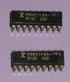
2114アクセススケッチ
1ワード=4ビットの2114を入手できたので、動作するか
を調べてみました。
 ピンアサインが不明だと、接続できないので手持ちの
参考書籍で掲載されているZ80関係の本を利用しました。
ピンアサインが不明だと、接続できないので手持ちの
参考書籍で掲載されているZ80関係の本を利用しました。
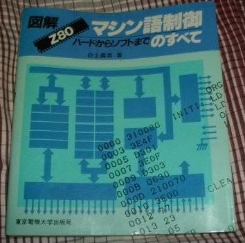 ピンアサインは、以下となっています。
 Arduinoに接続するには、次の3種の信号線群に分けて
考えます。
Arduinoに接続するには、次の3種の信号線群に分けて
考えます。
アドレスは動作テストができればよいので、カウンタICを
挟んで2114と接続します。1kワードとなるので10ビット
以上の出力をもつ、CMOSの4040を使います。
 カウンタはリセット(ゼロクリア)と+1処理だけができると
よいので、ポートCのPC0、PC1を使います。
カウンタはリセット(ゼロクリア)と+1処理だけができると
よいので、ポートCのPC0、PC1を使います。
 データは、ポートBのPB3からPB0の4ビットを使います。
 制御は、nCS、nWEがあればよいので、ポートCのPC3、PC2の
2ビットを使います。
制御は、nCS、nWEがあればよいので、ポートCのPC3、PC2の
2ビットを使います。
 接続仕様を決めたので、ポートの初期値と入出力方向を
定義します。
/* initialize PORT values */
PORTB = 0x00 ;
PORTC = 0x0e ;
PORTD = 0x01 ;
/* initialize PORT directions */
DDRB = 0xff ;
DDRC = 0xff ;
DDRD = 0xfe ;
4040の制御には、PC1(CLK)、PC0(RST)を使います。
リセットは正論理、クロックは負論理として制御用
に、2関数を定義します。
#define RST_BIT 0
#define CLK_BIT 1
void rst_cnt(void)
{
PORTC |= (1 << RST_BIT);
PORTC &= ~(1 << RST_BIT);
}
void clk_cnt(byte x)
{
if ( x ) { PORTC |= (1 << CLK_BIT); }
else { PORTC &= ~(1 << CLK_BIT); }
}
4040が、アドレスのゼロクリア、+1を担当するので
メモリの制御を担当する関数を定義します。
#define SIG_ENABLE 0
#define SIG_DISABLE 1
#define WE_BIT 2
#define CS_BIT 3
void cs_2114(byte x)
{
if ( x == SIG_ENABLE ) { PORTC &= ~(1 << CS_BIT); }
else { PORTC |= (1 << CS_BIT); }
}
void we_2114(byte x)
{
if ( x == SIG_ENABLE ) { PORTC &= ~(1 << WE_BIT); }
else { PORTC |= (1 << WE_BIT); }
}
メモリにデータをライトするには、次のタイミングチャートに
従って、信号線をON、OFFします。
接続仕様を決めたので、ポートの初期値と入出力方向を
定義します。
/* initialize PORT values */
PORTB = 0x00 ;
PORTC = 0x0e ;
PORTD = 0x01 ;
/* initialize PORT directions */
DDRB = 0xff ;
DDRC = 0xff ;
DDRD = 0xfe ;
4040の制御には、PC1(CLK)、PC0(RST)を使います。
リセットは正論理、クロックは負論理として制御用
に、2関数を定義します。
#define RST_BIT 0
#define CLK_BIT 1
void rst_cnt(void)
{
PORTC |= (1 << RST_BIT);
PORTC &= ~(1 << RST_BIT);
}
void clk_cnt(byte x)
{
if ( x ) { PORTC |= (1 << CLK_BIT); }
else { PORTC &= ~(1 << CLK_BIT); }
}
4040が、アドレスのゼロクリア、+1を担当するので
メモリの制御を担当する関数を定義します。
#define SIG_ENABLE 0
#define SIG_DISABLE 1
#define WE_BIT 2
#define CS_BIT 3
void cs_2114(byte x)
{
if ( x == SIG_ENABLE ) { PORTC &= ~(1 << CS_BIT); }
else { PORTC |= (1 << CS_BIT); }
}
void we_2114(byte x)
{
if ( x == SIG_ENABLE ) { PORTC &= ~(1 << WE_BIT); }
else { PORTC |= (1 << WE_BIT); }
}
メモリにデータをライトするには、次のタイミングチャートに
従って、信号線をON、OFFします。
 データをライトする場合、次のシーケンスを実行します。
- アドレス、データを出力
- nCSを'L'に下げる
- nWEを'L'に下げる
- nWEを'H'に上げる
- nCSを'H'に上げる
関数にまとめます。
void put_memory(byte xdat)
{
/* put data */
PORTC &= 0xf0 ;
PORTC |= ((xdat >> 4) & 0x0f) ;
PORTB &= 0xf0 ;
PORTB |= (xdat & 0x0f) ;
/* enable nCS */
cs_2114(SIG_ENABLE) ;
/* enable nWE */
we_2114(SIG_ENABLE) ;
/* disable nWE */
we_2114(SIG_DISABLE) ;
/* disable nCS */
cs_2114(SIG_DISABLE) ;
}
アドレスは、ゼロクリアと+1の操作しかないので
関数put_memoryの外で処理します。
データリードのタイミングチャートから
シーケンスを考えます。
- アドレス
- nCSを'L'に下げる
- データ取得
- nCSを'H'に上げる
関数にまとめます。
byte get_memory()
{
byte dh ;
byte dl ;
/* change port direction */
DDRC = 0xf0 ;
DDRB = 0xf0 ;
/* enable nCS */
cs_2114(SIG_ENABLE) ;
/* get upper nibble */
dh = PINC & 0x0f ;
/* get lower nibble */
dl = PINB & 0x0f ;
/* disable nCS */
cs_2114(SIG_DISABLE) ;
/* change port direction */
DDRC = 0xff ;
DDRB = 0xff ;
return( (dh << 4) | dl ) ;
}
シリアルポートを利用して、Arduinoにコマンドを
与えて、メモリの操作をしていきます。
コマンドは、以下としました。
- ? help
- H set SRAM contents as 'FF'
- L clear SRAM contens as '00'
- S show SRAM contents
コマンドを決めると、インタプリタを定義できます。
if ( uflag == ON ) {
/* clear flag */
uflag = OFF ;
/* new line */
crlf();
/* get command */
cmd = *(sbuf+0) ;
/* judge */
if ( cmd == '?' ) { show_help(); }
/* set SRAM contents as 'FF' */
if ( cmd == 'H' ) {
/* address zero clear */
rst_cnt();
/* repeat */
for ( cnt = 0 ; cnt < 1024 ; cnt++ ) {
/* set data */
put_memory(0xff) ;
/* increment */
clk_cnt( ON );
clk_cnt( OFF );
}
}
/* clear SRAM contens as '00' */
if ( cmd == 'L' ) {
/* address zero clear */
rst_cnt();
/* repeat */
for ( cnt = 0 ; cnt < 1024 ; cnt++ ) {
/* set data */
put_memory(0x00) ;
/* increment */
clk_cnt( ON );
clk_cnt( OFF );
}
}
/* show SRAM contents */
if ( cmd == 'S' ) {
/* address zero clear */
rst_cnt();
/* repeat */
*(msg+2) = 0 ;
for ( cnt = 0 ; cnt < 1024 ; cnt++ ) {
/* get data */
tmp = get_memory() ;
/* convert */
*(msg+0) = get_hex( (tmp >> 4) & 0x0f ) ;
*(msg+1) = get_hex( tmp & 0x0f ) ;
/* show */
rs_puts( msg );
/* new line */
if ( (cnt % 16) == 15 ) { crlf() ; }
/* increment */
clk_cnt( ON );
clk_cnt( OFF );
}
}
}
コマンドインタプリタ内部で利用している
関数を定義します。
void rs_putchar(char x)
{
Serial.write(x);
}
void rs_puts(char *x)
{
while ( *x ) {
rs_putchar(*x);
x++ ;
}
}
void crlf(void)
{
rs_putchar('\r');
rs_putchar('\n');
}
void show_help(void)
{
rs_puts("? help"); crlf();
rs_puts("H set SRAM as FF"); crlf();
rs_puts("L set SRAM as 00"); crlf();
rs_puts("S show SRAM contents"); crlf();
}
byte get_hex(char x)
{
byte result ;
/* default */
result = 0 ;
/* convert */
if ( '0' <= x && x <= '9' ) { result = x - '0' ; }
if ( 'A' <= x && x <= 'F' ) { result = x - 'A' + 10 ; }
if ( 'a' <= x && x <= 'f' ) { result = x - 'a' + 10 ; }
return result ;
}
必要な関数は揃ったので、スケッチを定義します。
ただし、2114を2個利用し8ビットデータ幅をもつ
メモリとします。
#define OFF 0
#define ON OFF+1
#define WE_BIT 5
#define CS_BIT 4
#define RST_BIT 5
#define CLK_BIT 4
#define SIG_ENABLE 0
#define SIG_DISABLE 1
#define BSIZE 8
#define MASK0F 0x0f
#define MASKF0 0xf0
#define MASKFF 0xff
#define LAST 1024
byte uflag ;
char sbuf[BSIZE] ;
byte sindex ;
char cmd ;
void rs_putchar(char x)
{
Serial.write( x );
}
void rs_puts(char *ptr)
{
while ( *ptr ) {
rs_putchar( *ptr );
ptr++ ;
}
}
void crlf()
{
rs_putchar('\r');
rs_putchar('\n');
}
void show_help()
{
rs_puts("? help"); crlf();
rs_puts("H set SRAM as FF"); crlf();
rs_puts("L set SRAM as 00"); crlf();
rs_puts("S show SRAM contents"); crlf();
}
byte get_hex(char x)
{
byte result ;
/* default */
result = 0 ;
/* convert */
if ( '0' <= x && x <= '9' ) { result = x - '0' ; }
if ( 'A' <= x && x <= 'F' ) { result = x - 'A' + 10 ; }
if ( 'a' <= x && x <= 'f' ) { result = x - 'a' + 10 ; }
return result ;
}
void rst_cnt()
{
PORTC |= (1 << RST_BIT);
PORTC &= ~(1 << RST_BIT);
}
void clk_cnt(byte x)
{
if ( x ) { PORTC |= (1 << CLK_BIT); }
else { PORTC &= ~(1 << CLK_BIT); }
}
void cs_2114(byte x)
{
if ( x == SIG_ENABLE ) { PORTC &= ~(1 << CS_BIT); }
else { PORTC |= (1 << CS_BIT); }
}
void we_2114(byte x)
{
if ( x == SIG_ENABLE ) { PORTC &= ~(1 << WE_BIT); }
else { PORTC |= (1 << WE_BIT); }
}
void put_memory(byte xdat)
{
/* put data */
PORTC &= MASKF0 ;
PORTC |= ((xdat >> 4) & MASK0F) ;
PORTB &= MASKF0 ;
PORTB |= (xdat & MASK0F) ;
/* enable nCS */
cs_2114(SIG_ENABLE) ;
/* enable nWE */
we_2114(SIG_ENABLE) ;
/* disable nWE */
we_2114(SIG_DISABLE) ;
/* disable nCS */
cs_2114(SIG_DISABLE) ;
}
byte get_memory()
{
byte dh ;
byte dl ;
/* change port direction */
DDRC = MASKF0 ;
DDRB = MASKF0 ;
/* enable nCS */
cs_2114(SIG_ENABLE) ;
/* get upper nibble */
dh = PINC & MASK0F ;
/* get lower nibble */
dl = PINB & MASK0F ;
/* disable nCS */
cs_2114(SIG_DISABLE) ;
/* change port direction */
DDRC = MASKFF ;
DDRB = MASKFF ;
return( (dh << 4) | dl ) ;
}
void send_memory(byte x)
{
word cnt ;
/* address zero clear */
rst_cnt();
/* repeat */
for ( cnt = 0 ; cnt < LAST ; cnt++ ) {
/* set data */
put_memory( x ) ;
/* increment */
clk_cnt( ON );
clk_cnt( OFF );
}
}
void show_memory()
{
word cnt ;
byte tmp ;
char msg[3] ;
/* address zero clear */
rst_cnt();
/* repeat */
for ( cnt = 0 ; cnt < LAST ; cnt++ ) {
/* get data */
tmp = get_memory() ;
/* convert */
*(msg+0) = get_hex( (tmp >> 4) & MASK0F ) ;
*(msg+1) = get_hex( tmp & MASK0F ) ;
/* show */
rs_puts( msg );
/* new line */
if ( (cnt % 16) == 15 ) { crlf() ; }
/* increment */
clk_cnt( ON );
clk_cnt( OFF );
}
}
void setup()
{
/* initialize serial port*/
Serial.begin(9600);
sindex = 0 ;
/* initialize PORT values */
PORTB = 0x00 ;
PORTC = 0x0e ;
PORTD = 0x01 ;
/* initialize PORT directions */
DDRB = 0xff ;
DDRC = 0xff ;
DDRD = 0xfe ;
/* clear flags */
uflag = OFF ;
}
void loop()
{
/* command interpreter */
if ( uflag == ON ) {
/* clear flag */
uflag = OFF ;
/* new line */
crlf();
/* get command */
cmd = *(sbuf+0) ;
/* set SRAM contents as 'FF' */
if ( cmd == 'H' ) { send_memory( MASKFF ) ; }
/* clear SRAM contens as '00' */
if ( cmd == 'L' ) { send_memory( 0x00 ) ; }
/* show SRAM contents */
if ( cmd == 'S' ) { show_memory() ; }
}
}
void serialEvent()
{
char ch;
if ( Serial.available() > 0 ) {
/* get 1 charactor */
ch = Serial.read();
/* store */
sbuf[sindex] = ch ;
/* increment */
sindex++ ;
/* judge */
if ( ch == '\r' ) {
sindex = 0 ;
uflag = ON ;
}
}
}
目次
前
次
